
The change in MCAS after the 2016 test flights from 0.6 degrees to 2.5 degrees is the smoking gun confirming that something must have occurred during these test flights which forced Boeing to make this radical change to MCAS. In this section, we will finally answer the question no one thus far has been able to answer: Why was such a radical change needed? How could Boeing engineers have made such a huge mis-calculation? The answer is turbulence – the most complex topic in all of physics. In this section, we will explain why even smart engineers might under-estimated the extreme effect that the turbulence of raising the engines one foot higher than it had been previously placed in the 737 NG would have on the 737 Max.
First, you need to understand that turbulence has been called the most important unsolved problem in physics. The American Nobel Prize Laureate for Physics Richard Feynman once described turbulence as “the most important unsolved problem of classical physics”, because an accurate mathematical equation of turbulence does not exist. We have quantum mechanical equations to describe the inner workings of the atom – but we do not have accurate equations for turbulence. In 2000, the Clay Mathematics Institute in Cambridge/Massachusetts offered one million US dollars to any mathematician who could provide an accurate equation for turbulence. So far, no one in the world has been able to solve this problem. Note the sudden and chaotic expansion:

Even the inventor of Quantum Mechanics, and the winner of the 1932 Nobel Prize in Physics, Werner Heisenberg once said that if he were allowed to ask God two questions, they would be, “Why quantum mechanics? And why turbulence?” Heisenberg said he was pretty sure God would be able to answer the first question (implying that not even God can explain turbulence).
Given that not even God understands turbulence, it should not be too surprising that Boeing engineers might have under-estimated the adverse effect of turbulence when they designed the 737 Max.
There are two ways that engineers guard against turbulence. The first and most common way is to avoid turbulence as much as possible. This is why no previous version of the 737 had placed the engine so close to the top of the wing. Putting the engine at or above the wing would create unpredictable turbulence exactly where you do not want it – at the top of the all important wings where it might have huge and difficult to calculate effects such as pivoting the plane around the center of gravity.
Unfortunately, there was not enough room to put the new much bigger engines well under the wings – and Boeing executives insisted that the engine be moved up rather than redesign the entire plane to account for the bigger engines. So the engines were moved up about one foot – which as we will show later in this section, created a huge amount of turbulence right over the wings. Strike #1.
The second way to deal with turbulence is to build scale models and do wind tunnel testing. I have been unable to find any accounts of wing tunnel testing on the 737 max. Instead, what I have found is many accounts of Boeing executives insisting that development occur more rapidly because they were in a trillion dollar race with Airbus to produce a new airplane to compete with the Airbus A320 NEO (which did have room for the new engines under the wing). I therefore have concluded that either there was no wind tunnel testing at all – or if it did occur, it was not adequate. Instead, it is likely that Boeing engineers simply did computer simulations of lift and turbulence. Here is a picture of one of these simulations:
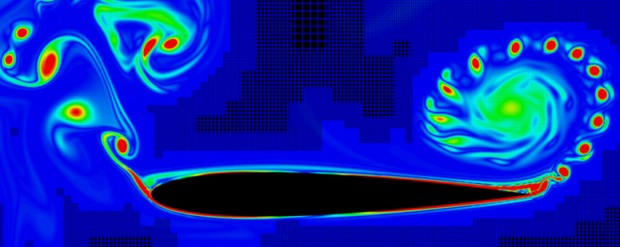
Based on these computer simulations, Boeing engineers simply estimated that the nose of the plane would rise slightly. They then came up with MCAS and a tail adjustment of 0.6 degrees as a solution to fix this problem. Strike #2.
Unfortunately computers have a difficult time predicting turbulence because all computers use equations. This is why the only good solution, besides avoiding turbulence, is to build scale models and do actual wind tunnel testing to simulate real world conditions like cross winds and icing on the wings.
It appears that Boeing simply took the initial drawings and built four actual 737 Max planes. These planes were completed in spring 2016 and then Boeing began doing real world test flights on a plane that had never existed before. At some point in the spring 2016, FAA regulations (which we quoted from in an earlier section) forced Boeing to do anti-stall maneuvers which placed the 737 Max at an angle of attack of nearly 20 degrees. As we will show in a moment, this angle of attack greatly increases the exposure of the new engines above the wings of the 737 Max - which then rapidly and unpredictably increases the turbulence just as the air flows over the center of gravity. The effect is a minor loss of lift in front of the center of gravity and a large loss of lift towards the tail of the plane – causing a huge pivot around the center of gravity and lifting the nose tremendously. Here is a picture from NASA showing how turbulence increases as it moves over a flat surface. Note the rapid increase from left to right:
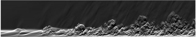
Imagine the center of gravity of the 737 Max being somewhere in the middle of this picture and you can understand why this problem could fool not only Boeing engineers but also any computer models they were relying on. Capturing, and predicting, the transition to turbulence is an ongoing challenge for engineers, physicists, mathematicians and computer programmers. There are many theories and many models. But none of them are really accurate. They should never be used in the real world where hundreds of lives are at stake.
I believe that during the required stall recovery tests in the Spring of 2016, Boeing engineers realized for the first time that they had a major problem. An MCAS adjustment of 0.6 degrees in the tail flap (5 degree change at the nose of the plane) simply was not enough to prevent the 737 Max from going into a catastrophe out of control stall. In short, the 737 Max could not pass the FAA Anti-Stall stability test.
At the same time, Boeing corporate executives were insisting that the 737 Max pass all FAA required tests as soon as possible. There was a lot of pressure put on the engineers in the Spring of 2016 because billions of dollars were at stake. It is likely that Boeing engineers first tried to double MCAS from 0.6 degrees to 1.2 degrees (pushing the nose of the plane down 10 degrees). Here is a picture of all of the computer equipment that was inside of one of these initial test flights. The stability tests were conducted from February 2016 to June 2016. The picture was taken on June 28, 2016 around the time that the change in MCAS was made.
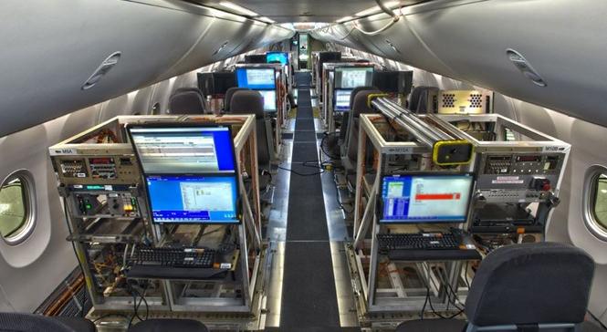
http://www.b737.org.uk/maxflttestprog.htm
Sadly, even 1.2 degrees of MCAS was not enough to prevent the 737 Max from going into an uncontrollable stall. Engineers then likely tried 1.8 degrees of MCAS. This did not work either. Eventually, engineers were forced to move MCAS all the way up to 2.5 degrees at the tail (20 degrees at the nose). They were even forced to add a repeat function to insure that the 737 Max was able to pass the FAA anti-stall test. Put in plain English, the plane had such a huge tendency to go nose up that a huge adjustment was needed to avoid nose up.
So what will the new 2019 Boeing fix do by reducing the MCAS adjustment from what engineers felt was needed in June 2016? The answer is obvious. The new Boeing adjustment will reduce the chances of a nose dive by increasing the chances of a nose up stall – even though Boeing surely knows that stalling the 737 Max is just as likely to lead to loss of control of the airplane and crashing the airplane as a nose down dive.
It does not really matter if the new MCAS setting is limited to 1 degree or 2 degrees of adjustment instead of 2.5 degrees. When a plane is this unstable, you pick your poison. Do you want to die in a crash caused by nose down diving or nose up stalling? Either way, within months of starting to fly again, some hapless or poorly trained pilot will allow the 737 Max to get into a nose up position. It will stall and then crash. This is why I am so certain that the 737 Max will have a crash within a matter of months after it is rubber stamped to fly again by the FAA. But to better understand why stalls are so dangerous, we will next take a closer look at the narrow range of conditions needed to maintain a Stable Flight Envelope. If you do not like math, you may want to skip the rest of this section as things are about to get a little complicated.
What is Needed to Maintain a Flight Envelope
Most people have no idea what kind of complex forces are involved when a modern commercial airplane is flying at hundreds of miles an hour and carrying 200 people and all of their luggage in a plane that is half the length of a football field. Much of the process is not only automated, it is power driven using special hydraulic devices.
Imagine trying to turn or stop your car while driving at 70 MPH on the freeway. It is hard enough. Now imagine having to do this without power brakes and power steering. It is almost impossible. Now imagine multiplying all of these forces by a factor of 100 – that is what makes modern airplanes so complex.
Add to this the problems of lift versus turbulence and the changing density of the air when ascending from sea level to 20,000 feet and what you get is a massive amount of complex equations and force vectors. From the moment a plane speeds up on the runway and takes off, to the moment it lands, it is subjected to a huge range of forces. These forces need to be kept inside a range of values called the Flight Envelope.
Understanding how Lift can suddenly change to Stall
While these values change with speed and elevation, here we will only look at that part of the flight envelope needed to avoid stalling and the crucial effect of the angle of attack. There is a simple test you can do while driving your car down the freeway that will help you understand how rapidly lift can change to stall. Pretend your hand is the wing of an airplane. Stick you hand out the window of you car with your palm down and your hand level to the ground. You hand is at a low angle of attack. You hand does not go up or down because there is no lift. Next, tilt your hand a bit to expose a little of your palm to the wind. Suddenly, your hand wants to go up due to a force called lift. Finally, keep increasing the amount of your palm exposed to the wind. At first, the lift force will increase. But as some point, your hand will suddenly be forced to go down and may even smack into the side of your car due to the sudden change in force. Here is a picture of a child learning the difference between lift and stall:

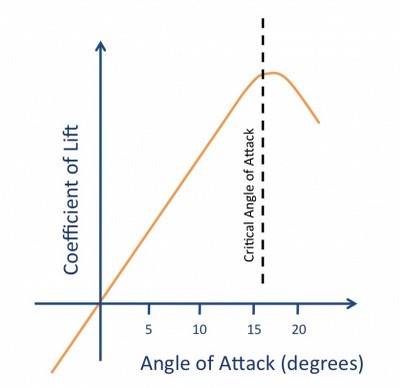
Here is a graph of the sudden change from lift to stall as the angle of the wing in relationship to the airflow changes:
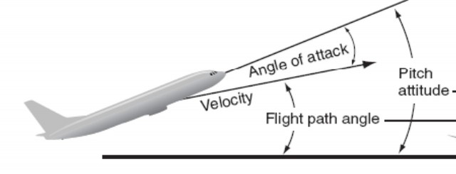
The danger of a plane stalling is at its greatest shortly after takeoff as the plane is trying to gain altitude – which means that the plane must be in a nose up position. The technical term for a nose up position is a positive angle of attack. This is not the same as the angle of the airplane compared to level ground. Instead it is the angle of the airplane compared to the angle of the wind going over the wing – which is in turned related to the flight path angle of the airplane in terms of its forward progress. Below is one of the best diagrams I have been able to find showing this difference:
http://www.alphasystemsaoa.com/assets/PDFs/articles/Angle-of-Attack-APS-Training.pdf
Note that the plane above, shortly after take off, is moving forward at the Flight Path Angle. But the plane is also tilted slightly above the Flight Path Angle. The angle between the plane and the ground is called the Pitch Angle. But what matters in terms of avoiding a stall is not the pitch angle. Rather what matters is the Angle of Attack (AOA) which is the difference between Pitch Angle and the Flight Path Angle. Note that the above diagram assumes that there is no wind and that the wind angle over the wing is therefore the same as the Flight Path Angle. Wind that is at a different angle from the Flight Path Angle reduces the margin of safety in the Flight Envelope.
The reason taking off is so difficult in terms of the danger of stalling is that up to a certain point, where the nose is up about 17 degrees, an airplane will get more lift if it has a higher angle of attack. Most airplanes come very close to 17% shortly after takeoff in order to gain altitude rapidly. However, beyond 20%, the lift is suddenly lost and the airplane will spin and roll out of control.
Note that maximum lift is achieved at an Angle of Attack of about 17 degrees. Beyond this value, lift is suddenly replaced by turbulence. Think of smooth air flowing over the wing as good but bouncy air flowing over the wing as bad. Here is a diagram showing the difference between good lift and bad turbulence.
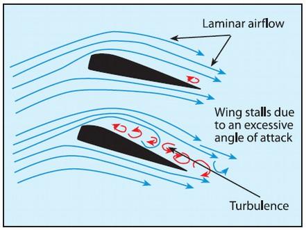
Turbulence eliminates lift causing the plane to stall. Here is an example of lift versus stalling with the entire airplane in the picture:
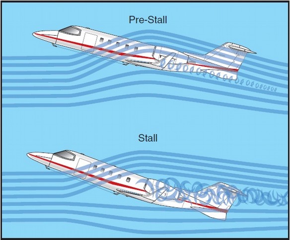
So smooth airflow is good for lift and turbulent airflow is bad. This is basic physics. Unfortunately, Boeing went down a path that eventually caused it to ignore the laws of physics.
Why the 737 Max Engine was moved too far forward and too far up
The first 737 designed in 1965 was intended to have 100 seats and fly up to 1000 miles. To speed up design work, Boeing used 60% of the structure and systems of its previous 727. http://www.wikiwand.com/en/Boeing_737
Here is a bottom up picture showing the relationship of the engine to the wing in the original 737 produced in the 1970:
Above is the 737-200 produced in 1970. You can see that the two engines are almost directly under the two wings. In 1988, the production of 737-200 was ended after making 1,114 of planes of this model.
By 1979, as oil was becoming more expensive, it was becoming apparent that more efficient engines would require much more space in diameter compared to the previous engines. There was not enough room under the wing of the 737 for these bigger engines.
Boeing should have recognized in 1979 that the trend towards bigger diameter, high bypass engines would continue and therefore should have designed a plane that was much higher off the ground in 1979. But instead, Boeing did not want to invest in a new plane design. So they began making mistakes that would eventually lead to the 737 Max disaster.
Their first mistake in 1979 was to move the engine more in front of the wing.
They also moved parts of the engine to the side of the fan. This gave the 737-300 engine the appearance of a hamster pouch. Here is a picture of the forward mounted hamster pouch engines:
The first flight of the 737-300 (now called the 737 Classic) was February 24, 1984 and it was certified as safe by the FAA 6 months later. By 1990, Boeing for the first time faced competition from the Airbus A320 – a European made plane that was designed to be higher off the ground in order to accommodate a new generation of bigger engines.
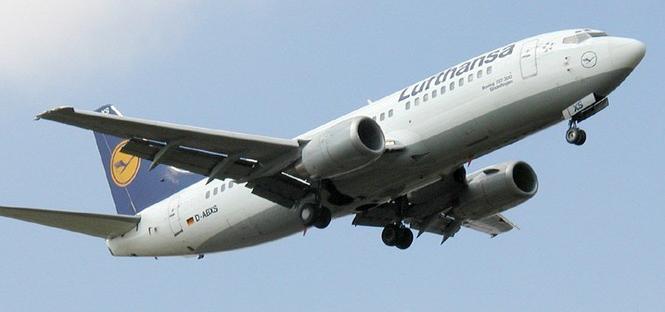
Boeing therefore began to design a more fuel efficient version of the 737 called the 737- Next Generation or 737 – NG for short. The wing span was increased by 16 feet – increasing the area under the wing by 25%. The first 737-700NG was flown on July 31, 1997 and certified by the FAA in 1998. The 737-700NG had even flatter engine undersides than the 737-300.
Here is a picture of the bottom of the 737-700NG with the flat bottom engines:
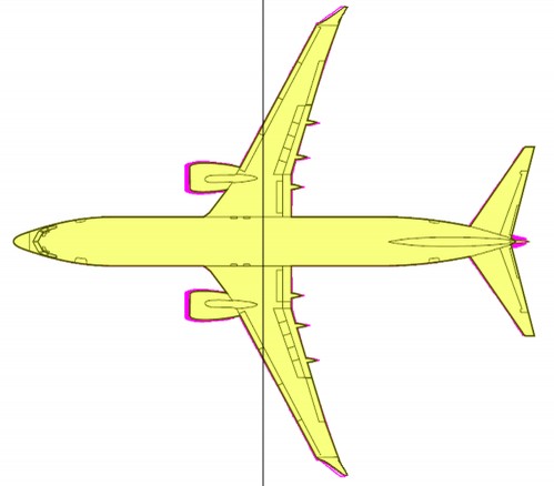
Now let’s look at the 737 Max with the big engines placed forward of the wing and above the wing compared to the previous 737 NG:
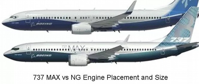
Notice that the NG engine had also been moved forward and up compared to the 737 Classic. So the 737 NG was already slightly more unstable than the 737 Classic.
The 737 Max engine was moved about 12 more inches forward and about 12 more inches up. Both moves were bad because they both add lift and push the nose of the plane up. Remember that once the angle of attack is exceeded, the nose will start to pitch up even more – which leads to the out of control death spiral. Therefore in weakening MCAS, all Boeing is really doing is changing the 737 from a plane that has a tendency to go into a steep dive into a plane that has a tendency to stall. Either way, eventually another Boeing 737 Max is going to crash and when it does, it will be all over for Boeing.
Why moving the engine forward in front of the wing creates instability
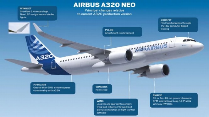
On December 1, 2010, Airbus announced a new version of the A320 called the A320 NEO which would use a much bigger and more fuel efficient engine called the LEAP engine. The new LEAP 1A engines featured an 11 to 1 bypass instead of the previous 6 to 1 bypass ratio resulting in a 16% savings in fuel consumption. (the LEAP 1B engines used on the Boeing 737 Max has only a 9 to 1 bypass ratio due to a smaller diameter fan and therefore only a 12% savings on fuel consumption). However, this increase in fuel efficiency required the engines to be much larger in diameter than previous engines. As the following table shows, the diameter of the LEAP 1B engine is about 24 inches greater in height than the diameter of the engine used in the 737 NG.
Table of Boeing 737 Engine Increase in Diameter
| Boeing Model |
Year Certified |
Engine |
Fan Diameter (inches) |
HT - Engine Diameter |
Engine Ground Clearance |
| 737 100 - 200 |
1967 |
P & W JT8D |
49 |
60 |
17 to 20 inches |
| 737 Classic |
1984 |
CFM56 - 3 |
60 |
71 Hamster |
15 to 18 inches |
| Airbus A320 |
1987 |
CFM56 - 5 |
68 |
89 |
24 inches |
| 737 NG |
1998 |
CFM56 - 7 |
61 |
72 Hamster |
15 to 18 inches |
| 737 Max |
2017 |
CFM – LEAP 1B |
69 |
89 |
15 to 17 inches |
| Airbus A320 NEO |
2016 |
CFM – LEAP 1A |
78 |
96 |
18 inches |
Note 2: some reports have indicated that the LEAP 1B Engine height is only 12 inches greater than the previous engine. However, the following source indicates that while the fan is 11 inches higher, the LEAP 1B engine is 17 inches higher. https://en.wikipedia.org/wiki/CFM_International_LEAP
How far forward and how far up did Boeing place the new LEAP engines?
Sadly, Boeing has not publicly stated how far forward and how far up they placed the new LEAP 1 B engines. Apparently, no reporter has ever bothered to ask or do the needed research. We are therefore forced to guess this crucial information. Here are some diagrams indicating the location and ground clearance of the LEAP engine on the Airbus A 320 NEO and 737 Max compared to previous engines on previous planes.
737 Max:
http://www.boeing.com/assets/pdf/commercial/airports/acaps/737MAXbrochure.pdf
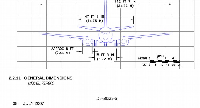
737 NG:
http://www.boeing.com/assets/pdf/commercial/airports/acaps/737.pdf
The Boeing 737 wing is about one foot thick at the engine
Here is a diagram of the Airbus A320 NEO:
According to the following document, the A320-200 has 24 inches of clearance from the bottom of the engines to the ground and the A320-NEO has 18 inches of clearance. https://www.airbus.com/content/dam/corporate-topics/publications/backgrounders/techdata/aircraft_characteristics/Airbus-Commercial-Aircraft-AC-A320.pdf
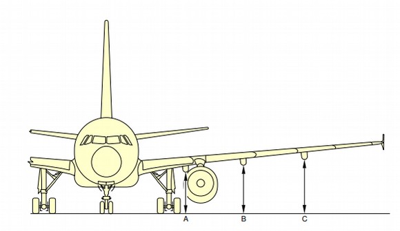
Adding in the diameters of the engines, it appears that the top of the A320 engine is 24 inches plus 83 inches = 107 inches. It was also located about 18 inches below the top of the wing. Here is a front view of the A320. Note the space below the wing at Point A. :
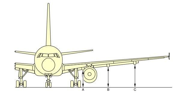
The top of the A320 NEO engine is 18 inches plus 89 inches = 107 inches. It is located 7 inches below the top of the wing. Here is a front view of the A320 NEO. The NEO has no space below the wing at Point A. But the engine is still several inches under the top of the wing:
Equally important, the wing on the Airbus A320 and A320 NEO is slightly further towards the back of the plane – meaning that an MCAS system is not needed to prevent the nose of the A320 NEO from rising.
Either Airbus got extremely lucky or they were able to predict in 1980 that engines would eventually get bigger over time. Either way, in the 1980’s, Airbus designed the A320 with several inches of extra room under the wing and they were able to easily change from the A320 to the A320 NEO without significant modifications.
Because the A320 was already much further off the ground, there was no need to change the overall design of the A320 to accommodate the bigger engine. Its first test flight was in September 2014 and first commercial flight was January 25 2016 – a full year ahead of the Boeing 737 Max. As of April, 2019, Airbus has received 6,500 orders for the Neo and delivered 778 planes. The Airbus Neo does cost about 10% more than the Boeing 737 Max ($110 million versus $100 million). But they are also more fuel efficient was they have bigger engines.
The difference between the LEAP engine and the previous engine was about 24 inches. There was simply no way that the original 737 design could be made to fit this new LEAP engine. Remember that Boeing had to alter the engine to a hamster shape and move the engine as far up and as far forward as possible just with their 737 NG just to accommodate the 11 inch increase from the original 737 to the 737 Classic.
So Boeing decided to move the engine even more forward and more up. The problem with moving the engine forward is that the engine itself acts as an extension of the wing – increasing lift more towards the front of the plane. While only moving forward a few inches, this is all it takes to force the teeter totter to tip too far towards the front of the plane. This destabilizing effect is minimal at a normal flying low angle of attack (less than 5 degrees). But it will increase dramatically when the airplane is climbing with an AOA above 15 degrees.
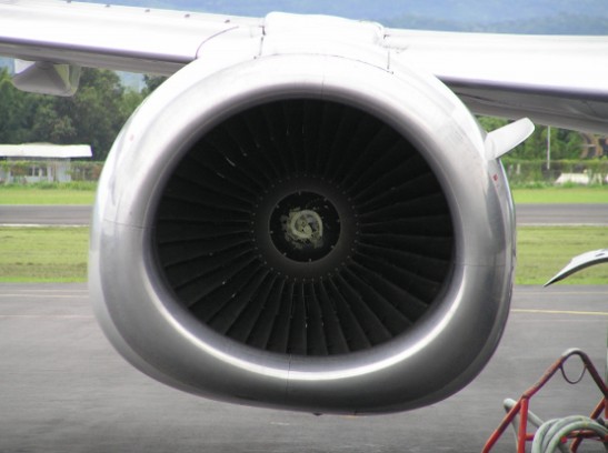
Here are some images of how far forward and how far up the new LEAP 1B engine is on the 737 Max. First is a closeup view showing how big the new LEAP engine is and how far forward it has been placed in front of the wing:
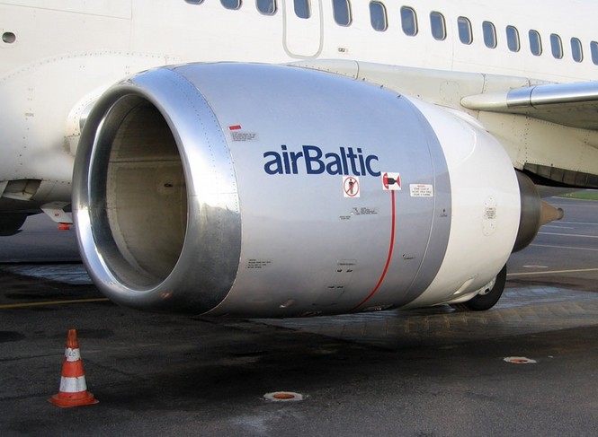
Another closeup view:
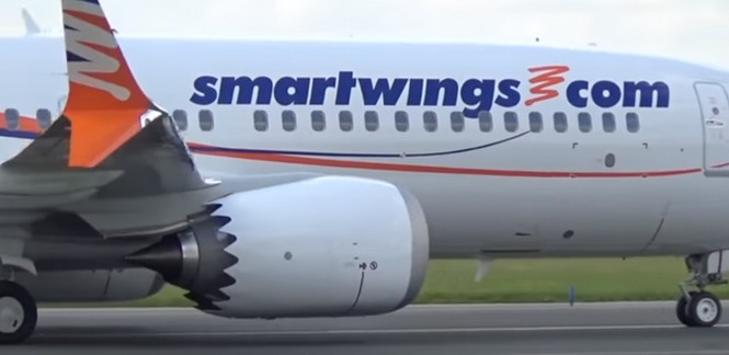
Here is a more distant side view:
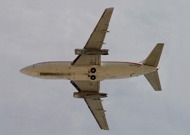
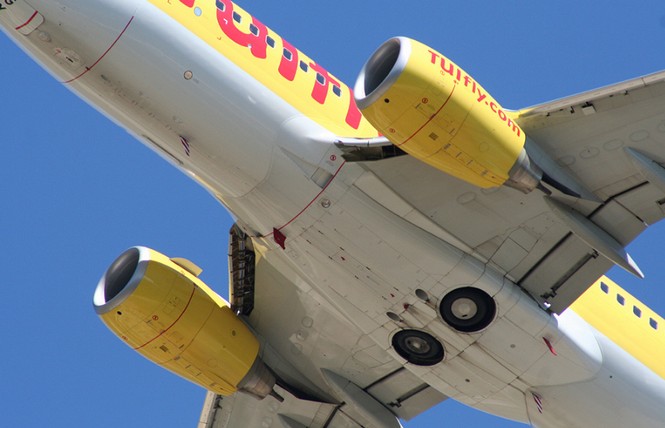
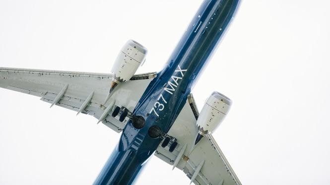
Here is a view of the underside of the 737 Max while in flight:
Here is a picture of the 737 Max Engine forward placement in relationship to the Center of Gravity:
Based on the above images, and the above calculations, I estimate that Boeing moved the 737 Max LEAP engines about one foot forward and one foot up compared to the placement of the previous 737 NG engines. I further estimate that the thickness of the wing where the engines are attached is about one foot.
Why moving the engine above the wing creates a lot of instability
It is likely that moving the engine above the wing is an even bigger danger than moving the engine more in front of the wing. This is because the irregular shape of the engine placed above the wing is certain to create more turbulence. Here is a closeup picture showing the placement of the 737 Max engine above the wing in comparison to the previous placement of the 737 NG engine:
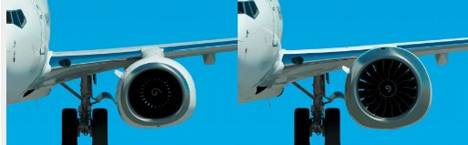
The above picture makes it appear as if the 737 Max engine is slightly below the wing. But remember that at takeoff and while climbing, the 737 Max is at a nose up angle. The more the nose is up, the higher the engine is in relationship to the wing and the greater the turbulence is created by the engine in relationship to the wing. Here is a picture of the 737 Max shortly after takeoff showing this problem. Note that from the moment the 737 Max leaves the ground, both engines are already several inches above the wings.
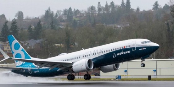
The turbulence created by placing the engines above the wings increases with speed and increases with the Angle of Attack. The 737 Max is the first commercial airplane to place the engine above the wing. It will likely be the last.
It is the fact that the 737 Max has the engine placed too far in front of and above the wing that leads to the conclusion that the 737 Max is the most unstable commercial airplane ever built. There is no solution for this problem other than to stop making the 737 Max and replace it with an entirely new airplane designed to be far enough off the ground so that the engines can be put in a more stable position. Oh, that would be the Airbus A320 Neo.
Equation for Lift of an airplane wing
The lift equation states that lift L is equal to the lift coefficient Cl times the density r times half of the velocity V squared times the wing area A.
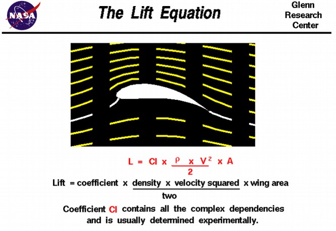
Lift depends on the density of the air, the square of the velocity, the air's viscosity and compressibility, the surface area over which the air flows, the shape of the wing, and the wing's inclination or angle to the flow. In general, the dependence on wing shape, inclination, air viscosity, and compressibility is very complex. One way to deal with complex dependencies is to characterize the dependence by a single variable. For lift, this variable is called the lift coefficient, designated "Cl." This allows us to collect all the effects, simple and complex, into a single equation… For given air conditions, shape, and inclination of the object, we have to determine a value for Cl to determine the lift.
For some simple flow conditions, aerodynamics can determine the value of Cl mathematically. But, in general, this parameter is determined experimentally. https://www.grc.nasa.gov/www/k-12/airplane/lifteq.html
Note that the lift is proportional to the area of the wing. Because the engine becomes part of the wing, moving the engine forward a few inches increases the area of the wing by a few inches. This is therefore a minor increase in the lift of the wing and can be offset by an MCAS change of 0.6 degrees in the tail flap. The above equation assumes that there is no turbulence and does not account for the angle of attack of the plane or wing.
Why there is no accurate equation for Turbulence
Turbulent flow is air motion characterized by chaotic changes in pressure and flow velocity. It is in contrast to laminar flow, which occurs when air flows in parallel layers… The fact that Boeing engines mis-calculated by a factor of 4 the amount of MCAS needed to offset the nose lift of the 737 Max is evidence that they were confronted with a very difficult math problem. Here we will briefly summarize some of the problems created by turbulence of placing the engine at the same level as the wing when the plane was level. https://royalsocietypublishing.org/doi/full/10.1098/rsta.2010.0332
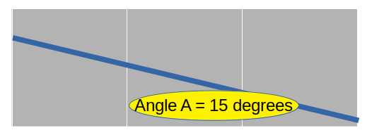
For the 737 NG, at an angle of attack of 15 degrees, assuming the engine was placed 3 feet in front of the wing, and the engine was placed 12 or more inches below the wing, the height of the engine exposed to turbulence would be minimal:
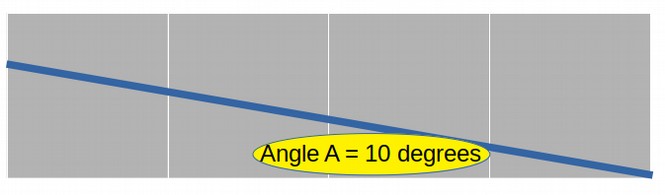
For the 737 Max, at an angle of attack of 10 degrees, assuming the engine was placed 4 feet in front of the wing, and was raised 12 inches to be even with the top level of the wing, the height of the engine exposed to turbulence is about 8 inches (4 times 0.176 feet = 0.7 feet = 8.4 inches):
For the 737 Max, at an angle of attack of 15 degrees, assuming the engine was placed 4 feet in front of the wing, and was raised 12 inches to be even with the top level of the wing, the height of the engine exposed to turbulence is about one foot (4 times 0.268 feet = 1.1 feet = 13 inches):
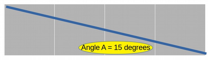
If the tangent of a right triangle is four (the ratio is one over four or 0.25) , then the smaller angle is 14.5 degrees. See this table. https://www.grc.nasa.gov/WWW/BGH/tabltan.html
Diagrams for 787 Max Engine Exposure over Wing related to area of diameter of circle
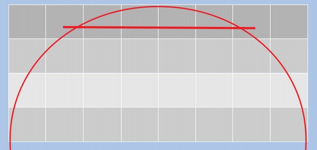
The737 Max engine has a diameter of about 88 inches. Here is a diagram of a cord of a half circle with a radius of 44 inches and a cord height of 11 inches. (Each box is an 11 inch square).
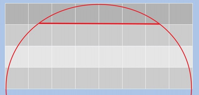
Here is a cord height of 8 inches (10 degree AOA):
Here is a cord height of 13 inches (15 degree AOA):
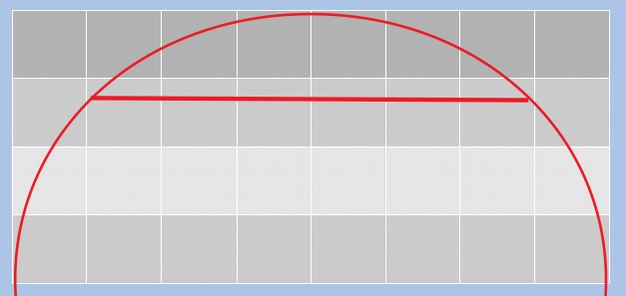
Note that there is a rapid increase in the area of the engine exposed to turbulence for every inch of engine raised above the wing (dark shaded area). This is why the engine should never have been raised above the wing. This was a huge error.
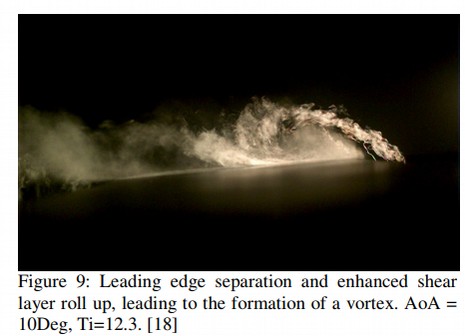
Here is a link to a paper which attempts to discuss turbulence in wind tunnel tests of small flying objects (drones). The forces are obviously much greater on a 737 Max but some of the principles discussed can apply. http://www.icas.org/ICAS_ARCHIVE/ICAS2012/PAPERS/970.PDF
Here is an image from this study. Note that the turbulence increases from the front of the wing (on the right) to the tail of the wing (on the left). This is due to the rolling nature of dynamic turbulence. Think of it as a series of rolling waves.
Here is another image showing the pressure increasing from the front of the wing (right) to the tail of the wing (left):
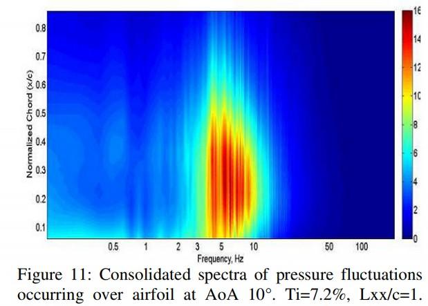
Now think of the wing of the 737 Max as a teeter totter pivoting around the center of gravity. The increase in turbulence (reduction in lift) will be greater on the back of the wing than it will be on the front of the wing.
The will greatly increase the ratio of the lift at the front of the plane. I believe that it is this extremely complex effect of turbulence that was missed in the initial calculations and was only discovered in 2016 during test flights of the actual Boeing 737 Max. The problem was not so much moving the engine forward. It was moving the engine up. This dynamic increasing effect of turbulence forced engineers to raise MCAS from 0.6 degrees with no repeat to 2.5 degrees – with a repeat function.
Boeing has now proposed to reduce MCAS to some lower un-announced value. But all this new change in MCAS will do is increase the risk of a crash resulting from a stall. The real problem is that the two new engines should never have been raised several inches. Boeing over-confidence caused them to build the world’s most unstable commercial airplane.
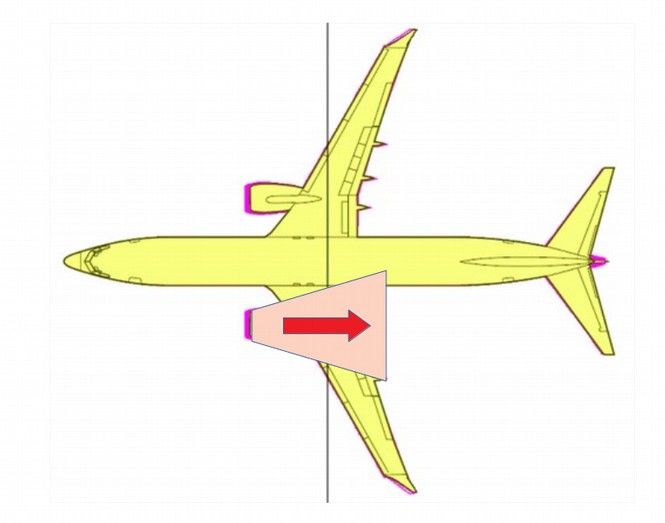
The Trouble with Torque
There is a third problem with moving the 737 Max engine up and forward. In addition to increasing lift in front of the center of gravity – pushing the nose up – and reducing lift with turbulence behind the center of gravity, the position of the new engines will also produce torque when the engines are revved up. This will also push up the nose of the plane and cause the 737 to spin like a top.
Here is what torque looks like:
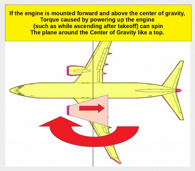
When the engines are too far away from the center of gravity, they create a torque, pushing the aircraft nose up when the engines are set at full power. This is dangerous because the angle of attack is already likely to be high during and after takeoff. Gunning the engine would cause the aircraft to raise the nose even higher resulting in a catastrophic and unrecoverable stall leading to a crash. This torque problem could be another reason MCAS was set for 2.5 degrees instead of 0.6 degrees.